
Internal Cold Mains Leak Detection in Sheffield
A cold mains leak in Sheffield was located beneath the kitchen floor using flow metering, acoustic listening, tracer gas, thermal imaging, an endoscope camera, and pressure testing, confirming water mains leak detection within a section of old copper pipework that had remained under mains pressure undetected. The work was carried out by engineer Brett Steele.




The original leak detection company, est. 2011
Facts
| Location | Sheffield |
|---|---|
| County | South Yorkshire |
| Leak Type | Water Mains Leak Detection |
| Property Type | Residential property |
| Detection Method | Flow Metering, Acoustic Listening Equipment, Tracer Gas, Thermal Imaging, Endoscope Camera, Pressure Testing |
| Outcome | Pin hole leak found in cold feed riser beneath kitchen floor, repaired. |
Symptoms

At a property in S17, the occupants had noticed a significant spike in water consumption alongside rising utility bills. A suspect leak noise could be heard on a 15mm copper pipe running behind wall tiles — a feed that supplies the upper floor.
All toilets had been inspected prior to the engineer's arrival and no issues were found there.
The ground floor sits over a void space, but this was inaccessible due to floor coverings. Various adaptations had been made to the pipework over the years, adding complexity to tracing the supply routes.
The combination of audible leak noise, unaccounted-for water usage, and an inaccessible sub-floor made this a case requiring systematic internal leak detection rather than a visual inspection alone.
The nature of the symptoms — hidden pipework, a tiled floor, and a redundant capped-off feed still under pressure — meant straightforward access to the leak point was not possible without targeted investigation first.
Methods Used

The investigation began with flow metering at the meter, which confirmed continuous uncontrolled usage. Step testing isolated the leak to the internal cold supply.
Acoustic profiling was then carried out across the ground floor, covering the utility room, downstairs toilet, and the cold feed rising to the upper floor — the riser off the kitchen area produced the highest levels of leak noise.
Tracer gas was introduced into the pipework and a full sweep of the property was conducted. High gas readings concentrated around the floor where the cold feed rises, directing excavations to that zone.
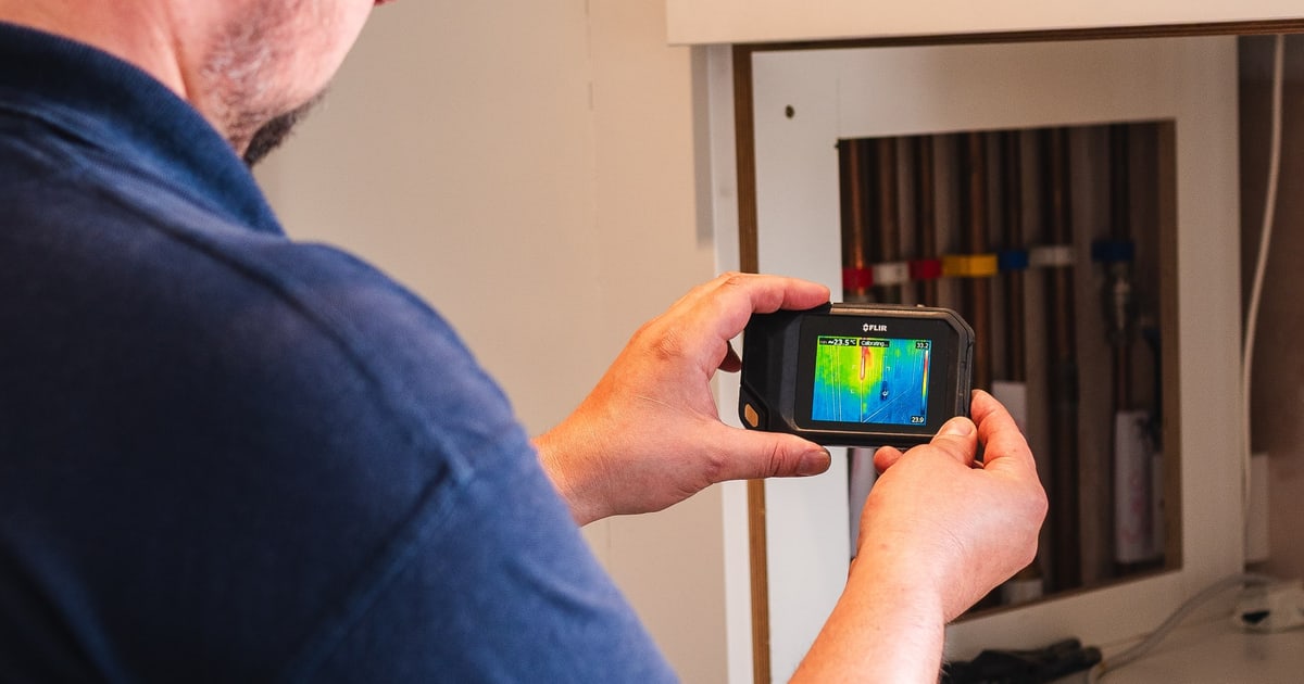
Because the floor contained wet underfloor heating, heat was applied first so that thermal imaging could map the pipe run beneath the tiles. This is the methodical approach that internal leak detection requires when pipework is concealed under multiple layers — each technique narrowing the search before any physical work begins.
A camera was used once the pipe was exposed to locate the exact leak point further along the run, directing the additional excavations needed to reach it.
Flow Metering. Monitored the meter to record uncontrolled usage of 1 litre over 1 minute 20 seconds, confirming an active leak before any further testing began.
Acoustic Listening Equipment. Profiled leak noise across the utility room, downstairs toilet, and cold feed riser, identifying the riser off the kitchen as the area of greatest suspect noise.
Tracer Gas. Introduced into the pipework and swept across the property; high readings concentrated around the floor at the cold feed riser, directing the excavation zone, and a 6-bar pressure retest confirmed the repair was sound.
Thermal Imaging. Used after heat was applied to the wet underfloor heating system to track the cold feed pipe run beneath the tiles and guide tile removal to the correct area.
Endoscope Camera. Deployed once the cold feed was exposed to locate the pin hole leak further along the pipe, identifying the precise point requiring additional excavation.
Pressure Testing. A tracer gas pressure test at 6 bar was performed after the repair; no pressure loss was recorded, confirming no further leaks on the supply.
Investigation Process
-
1Meter Monitoring
On arrival, the meter was monitored and recorded an uncontrolled usage of 1 litre over 1 minute 20 seconds, confirming an active leak was present.
-
2Step Testing
Step testing was carried out and proved the leak to be on the internal cold water supply to the property.
-
3Acoustic Profiling
Acoustic equipment was used to profile leak noise across the utility room, downstairs toilet, and cold feed to upstairs. The cold feed riser, located just off the kitchen, produced the highest levels of suspect leak noise.
-
4Tracer Gas Introduction and Sweep
Tracer gas was introduced into the pipework and a full sweep of the property was performed. High gas readings were found emitting from around the floor at the point where the cold feed rises to supply the upper floor.
-
5Thermal Imaging of Underfloor Pipework
The wet underfloor heating beneath the tiles was put under heat so that thermal imaging could track the pipe run, guiding the area of tile removal.
-
6Initial Excavation and Camera Survey
A section of floor tiles was removed in the area of high gas readings, exposing the cold feed pipe. A camera was used to locate the leak further along the pipe run than the gas readings alone had indicated.
-
7Additional Excavation and Leak Exposed
Further tiles were removed to expose the leak point — a pin hole that had developed in a section of old copper pipe that had been capped off further down the line but remained under pressure.
-
8Repair and Retest
The pin hole section was cut out and a push-fit coupler used to effect the repair; the redundant feed was capped off with a 15mm soldered cap end. A tracer gas pressure test at 6 bar recorded no loss, and no further uncontrolled usage was found.
Result & Outcome

The leak was located beneath the kitchen floor area, in a section of old 15mm copper pipe forming a cold feed riser to the upper floor. The pipe had developed a pin hole and, having been capped off further down the line at some earlier adaptation, remained under mains pressure — meaning it continued to leak undetected behind the tiled floor.
The leak point was cut out and repaired using a push-fit coupler. The redundant feed was permanently capped with a 15mm soldered cap end. A tracer gas pressure test at 6 bar confirmed no further pressure loss and no remaining uncontrolled usage, indicating the supply is now sound. This outcome reflects what precise internal leak detection achieves: the leak found, the redundant pipework secured, and the supply confirmed tight before any reinstatement work begins.
Before remedial work to make good the excavated area is carried out, it would be prudent to allow time for the foundations to dry out, given the moisture that will have accumulated from the ongoing leak.
Suspect a leak at your property?
ADI Leak Detection specialists investigate leaks like this across the UK every day. No find, no fee terms apply on qualifying jobs.