
Internal Cold Mains Leak Detection in Mablethorpe
A cold mains leak in Mablethorpe was located using pressure testing, tracer gas, acoustic listening, thermal imaging, and sectional isolation, with water mains leak detection confirming the source beneath the floor in the rear hallway, allowing the repair to be completed and the system tested clear on the same visit. Found by engineer Scott Hardcastle.




The original leak detection company, est. 2011
Facts
| Location | Mablethorpe |
|---|---|
| County | Lincolnshire |
| Leak Type | Water Mains Leak Detection |
| Property Type | Residential property |
| Detection Method | Pressure Testing, Tracer Gas, Acoustic Listening Equipment, Thermal Imaging, Sectional Isolation |
| Outcome | Leak found on hot pipe beneath hallway floor, repaired same day. |
Symptoms

The owner of a detached property in LN12 had no visible signs of a leak anywhere in the building — no damp patches, no wet walls, no obvious damage — yet water was being lost at a rate of approximately 20 litres per hour. The combi boiler was holding pressure normally, and there was nothing at the upstairs bathroom, downstairs shower room, or either WC to suggest where the water was going.
Because the loss was hidden and the customer had no indication of where to look, an internal leak detection survey was the appropriate course of action. Jobs like this, where there is measurable water loss but no visible trace, typically require a systematic approach to isolate sections of pipework before deploying specialist detection equipment.
It was also noted that the same area of the property had suffered a leak eight years earlier, though the customer was not aware this was relevant to the current situation.
Methods Used

The investigation began at the external meter to establish whether the leak was internal to the property or on the supply upstream. Once confirmed as internal, pressure testing with a rig attached to the outside tap was used to isolate the cold feed to the boiler — ruling it out — before identifying the leak as being on a hot pipe.
Tracer gas was then introduced into the pipework, and thermal imaging was used alongside acoustic equipment to narrow down the location before any floor was broken up.
This staged approach is standard practice in internal leak detection: eliminate sections of the system methodically, then concentrate detection effort only where the evidence points. By the time the floor was opened, the leak location had already been confirmed to a precise area in the rear hallway, minimising unnecessary excavation.
Pressure Testing. A pressure rig connected to the outside tap was used to isolate the cold feed to the boiler and confirm the leak was on the hot pipework rather than the cold supply.
Tracer Gas. Tracer gas introduced into the pipework migrated up through the floor in the rear hallway, identifying the section where the leak was located beneath the surface.
Acoustic Listening Equipment. Acoustic equipment was used after tracer gas confirmed the general area, pinpointing the exact position of the leak on the 15mm hot pipe before the floor was opened.
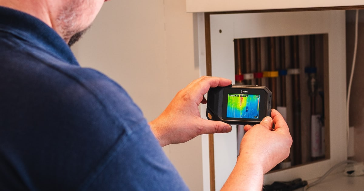
Thermal Imaging. Thermal imaging was deployed during the investigation to support the detection process and help identify any temperature differential associated with the escaping hot water beneath the floor.
Sectional Isolation. The cold feed to the boiler was isolated separately from the rest of the system to confirm definitively that the leak was on the hot side of the pipework.
Investigation Process
-
1External meter checked
The external meter was observed with the internal stopcock open and then closed. Movement was visible when the stopcock was open and stopped when it was closed, confirming the leak was internal from the stopcock onwards.
-
2Pressure rig connected to outside tap
A pressure rig was added to the outside tap to allow controlled isolation and pressure monitoring of sections of the internal pipework.
-
3Cold feed to boiler isolated
The cold feed to the boiler was isolated and the pressure gauge showed no drop, ruling out the cold supply as the source of the leak.
-
4Hot pipe identified as source
With the cold feed to the boiler reopened, pressure began to drop on the gauge, confirming the leak was on the hot pipework.
-
5Tracer gas introduced
Tracer gas was added to the pipework and was detected coming up through the floor in the rear of the hallway — the same area where a leak had occurred eight years previously.
-
6Acoustic equipment used to pinpoint
Acoustic detection equipment was used to narrow down the exact position of the leak within the area identified by the tracer gas.
-
7Floor broken up and leak found
With the customer's permission, the floor was opened in the rear hallway and the leak was found on a 15mm hot pipe feeding the basin in the downstairs WC.
-
8Pipe repaired and system tested
A small section of 15mm copper pipe and fittings were used to repair the leak. The system was tested, no further leaks were found, and no movement was visible on the external meter with everything reinstated.
Result & Outcome

The leak was found on a 15mm hot pipe beneath the floor in the rear hallway, feeding the basin in the downstairs WC. The location was consistent with a previous leak in the same area eight years earlier. A small section of copper pipe and fittings were used to carry out the repair on the same visit, and testing confirmed no further leaks were present anywhere on the system.
The precision achieved through internal leak detection — working from meter confirmation through pressure isolation, tracer gas, and acoustics — meant the floor opening was targeted and limited to the area where the leak had already been confirmed. There was no exploratory breaking up of multiple areas.
The exposed area will need time to dry out before pipes are covered, the floor is re-screeded, and tiles are reinstated. The customer has been advised to involve their insurer to assess the reinstatement work required.
Suspect a leak at your property?
ADI Leak Detection specialists investigate leaks like this across the UK every day. No find, no fee terms apply on qualifying jobs.