
Internal Cold Mains Leak Detection in East Dereham
An internal cold mains leak in East Dereham was located using thermal imaging, a damp meter, pressure testing, tracer gas, and visual inspection as part of water mains leak detection that identified two separate faults within the copper pipework. The work was carried out by engineer Ferenc Gulyas.




The original leak detection company, est. 2011
Facts
| Location | East Dereham |
|---|---|
| County | Norfolk |
| Leak Type | Water Mains Leak Detection |
| Property Type | Residential property |
| Detection Method | Thermal Imaging, Damp Meter, Pressure Testing, Tracer Gas, Visual Inspection |
| Outcome | Two leaks found in hot water pipework beneath kitchen and corridor floors. |
Symptoms

A property in NR19 presented with significant water damage visible along the hallway wall. The extent of the damage indicated that water had been escaping for some time, likely travelling through the structure before becoming apparent at the surface.
The building operates on a gravity-fed system for both hot and cold water pipework, as well as heating, with an indirect vented hot water cylinder housed in a corridor cupboard and an internal stopcock located beneath the kitchen sink unit.
The damage pattern pointed toward a concealed pipe leak somewhere between the bathroom and kitchen, but the exact source was not immediately identifiable through visual inspection alone. Given the gravity-fed arrangement and the spread of the damp, internal leak detection was required to isolate the system, test each circuit independently, and trace the leak to its precise origin beneath the floor.
The challenge was that the pipework runs beneath concrete, making the leak inaccessible without first confirming its location. The hot water circuit, the cold water supply to the bathroom, and the pipework routing through the corridor all had to be considered as potential sources.
Methods Used

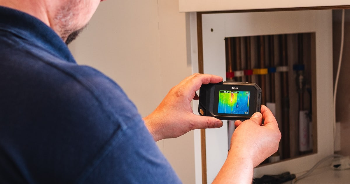
The investigation began with a full visual inspection of the property, followed by thermal imaging to map the pipe runs beneath the surfaces. The hot water pipework was clearly visible through the thermal camera, allowing the engineer to understand the routing before any testing began.
A damp meter was then used along the suspect areas, returning very high readings along the pipework path between the bathroom and kitchen.
Pressure testing was carried out in stages — first on the cold water pipework alone, which passed, ruling out the cold supply as the source. A 22mm full bore lever valve was then fitted to the hot feed pipework next to the cylinder, isolating the hot circuit for independent testing.
That test indicated a small leak somewhere along the hot line. Tracer gas was introduced to the isolated circuit, and internal leak detection using the gas detector pinpointed the leak location beneath the kitchen unit.
After the first repair and retest, the detector identified further readings in the corridor, leading to a second leak being found beneath the vinyl floor on the opposite side of the corridor wall.
Thermal Imaging. Used on arrival to trace the hot water pipe runs beneath the floor and wall surfaces, making the routing clearly visible before any physical investigation began.
Damp Meter. Applied along the pipework route between the bathroom and kitchen, returning very high readings that confirmed active moisture in the structure along that path.
Pressure Testing. Carried out separately on the cold and hot water circuits — the cold circuit passed, while the hot circuit indicated a small leak, allowing the source to be isolated to the hot pipework.
Tracer Gas. Introduced into the isolated hot water circuit to locate the precise leak points beneath the concrete floor, identifying the first leak under the kitchen unit and the second in the corridor on the opposite side of the wall.
Visual Inspection. Conducted on arrival to assess the visible water damage on the hallway wall and establish the system configuration, including the gravity-fed arrangement and the location of the cylinder and stopcock.
Investigation Process
-
1Visual Inspection on Arrival
The engineer carried out a full visual inspection of the property. Significant water damage was noted on the hallway wall, and the system was confirmed as gravity-fed with a vented indirect cylinder in the corridor cupboard and an internal stopcock under the kitchen sink.
-
2Thermal Imaging of Pipe Runs
A thermal imaging camera was used to identify the hot water pipework routing beneath the surfaces. The hot pipework was clearly visible, establishing the path from the cylinder through to the kitchen and bathroom areas.
-
3Damp Meter Survey
A damp meter investigation was carried out along the suspect areas. Very high damp readings were recorded along the pipework route passing from the bathroom through to the kitchen.
-
4Cold Water Pressure Test
The pressure test kit was connected to the outside tap wall plate elbow and a pressure test was carried out on the internal cold water pipework only. The test passed, ruling out the cold supply as the source of the leak.
-
5Hot Water Circuit Isolated
A 22mm full bore lever valve was fitted to the hot feed pipework next to the cylinder, isolating the hot water circuit for independent testing.
-
6Hot Water Pressure Test
A pressure test was carried out on the hot water pipework only. The test indicated a small leak somewhere along the line, confirming the hot circuit as the source.
-
7Tracer Gas Investigation — First Leak
Tracer gas was introduced to the isolated hot circuit. Despite a difficult trace, the gas detector identified the leak location beneath the kitchen unit. The unit was removed and the concrete floor was exposed.
-
8First Leak Located and Exposed
The leak was found on 15mm copper pipework directly beneath the wall between the kitchen and corridor. Access was also required from the corridor side to reach the full extent of the leaking section.
-
9First Repair and Retest
The leaking section of pipework was replaced with new 15mm copper pipe and soldered fittings. A retest was carried out, which indicated another leak was still present.
-
10Tracer Gas Investigation — Second Leak
The tracer gas detector identified further readings just on the other side of the corridor. The vinyl floor was lifted, exposing the concrete, and a second leak was identified in the pipework below.
-
11Second Repair and Final Retest
The second leaking section was replaced with new copper pipework. A final retest was carried out, which passed with no further leaks indicated. Water pressure was restored throughout the property.
Result & Outcome

Two separate leaks were found on the 15mm hot water copper pipework: the first directly beneath the kitchen unit at the base of the wall, and the second just across the corridor on the opposite side of the same wall. Both required concrete to be exposed — the kitchen unit was removed and vinyl flooring lifted in the corridor — to access the leaking sections. Each section was cut out and replaced with new copper pipework using soldered fittings, with pipework insulation applied. The final retest passed with no further leaks detected, and water pressure was restored to working order throughout the property.
The staged approach used here — pressure testing each circuit independently before introducing tracer gas — is standard practice in internal leak detection and was directly responsible for identifying the hot water system as the source without unnecessary disruption to the cold supply or heating circuit. The thermal imaging camera allowed the engineer to understand the pipe routing before any floor was opened, keeping the excavation targeted.
Both leaks were concealed beneath concrete and would not have been locatable through visual inspection or damp readings alone. The tracer gas investigation was critical in both instances, particularly for the second leak which produced only minor detector readings and required careful tracing across the corridor.
Suspect a leak at your property?
ADI Leak Detection specialists investigate leaks like this across the UK every day. No find, no fee terms apply on qualifying jobs.