
Underfloor Heating Leak Detection in Burnham-on-Crouch
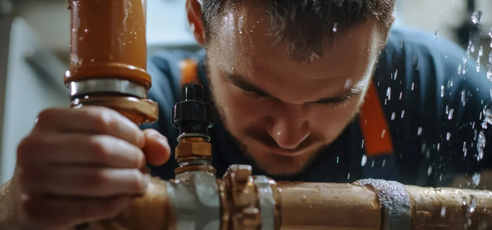
An underfloor heating leak in Burnham-on-Crouch was located using flow metering, pressure testing, thermal imaging, acoustic correlation, tracer gas, and a damp meter, with underfloor heating leak detection confirming the source beneath the kitchen floor at the threshold to the back hall. Found by engineer Mark Jones.
 CIPHE accredited
 WIAPS member


Facts
| Location | Burnham-on-Crouch |
|---|---|
| County | Essex |
| Leak Type | Underfloor Heating Leak Detection |
| Property Type | Residential property |
| Detection Method | Flow Metering, Pressure Testing, Thermal Imaging, Acoustic Correlation, Tracer Gas, Damp Meter |
| Outcome | Leak found under kitchen floor threshold, pipe replaced. |
Symptoms
A property in CM3 — a large detached house over two floors with unvented heating and hot water systems — had developed a significant leak within its underfloor heating pipework. Visible water damage was present to skirting boards and door surrounds, with discolouration to tile grout indicating prolonged moisture exposure.
Efflorescent salts were visible pushing through the concrete screed in the underfloor heating manifold cupboard, a clear sign of sustained water movement through the substrate.
The extent of the leak was not confined to the interior. A section of concrete block paving on the driveway, just inside the gate, had collapsed under the saturated ground, and a grass verge outside the gate was completely waterlogged.
These external signs pointed to a high-volume leak that had been tracking through the ground for some time.
An initial flow meter test confirmed the severity of the situation, indicating a leak rate of between 80 and 150 litres per hour. With underfloor heating leak detection required across both internal and external areas, the priority was to isolate the affected circuit and locate the precise failure point before further structural damage occurred.
Methods Used

The investigation began with a systematic isolation test to identify which circuit was responsible for the loss. This narrowed the leak to the water softener bypass supply feeding the kitchen — ruling out the main underfloor heating circuits and focusing attention on a specific pipework run beneath the kitchen floor.
With the leak zone identified, a multi-method approach was used to pinpoint the exact location without unnecessary excavation.
Thermal imaging, acoustic correlation, moisture testing, and tracer gas testing were all deployed in sequence. Each method contributed to building a precise picture of where the leak was occurring.
All four techniques converged on the same point: the threshold between the kitchen floor and the back hall. Underfloor heating leak detection work of this kind — where the pipe is embedded in screed and the leak may have tracked some distance from the source — depends on this combination of methods to avoid costly and disruptive over-excavation.
Once the location was confirmed with confidence, targeted excavation of the ceramic tiles and floor screed was carried out to expose the pipework.
Flow Metering. Used on arrival to quantify the leak rate, establishing a loss of between 80 and 150 litres per hour and confirming the leak was active and significant.
Pressure Testing. Used during isolation testing to identify the water softener bypass supply to the kitchen as the leaking circuit, ruling out other pipework runs.
Thermal Imaging. Scanned the kitchen floor to identify temperature anomalies in the screed consistent with a subsurface water escape at the threshold to the back hall.
Acoustic Correlation. Listened for the sound signature of escaping water through the floor substrate to corroborate the thermal imaging findings and refine the precise leak position.
Tracer Gas. Injected into the isolated pipe to detect gas emergence through the screed, providing a further independent confirmation of the leak location before excavation.
Damp Meter. Used to map moisture levels across the floor surface and skirting areas, helping to distinguish between the active leak site and areas of secondary water spread.
Investigation Process
-
1Initial site inspection
The engineer inspected visible damage on arrival: water-stained skirting boards, discoloured door surrounds, affected tile grout, salts in the manifold cupboard, collapsed driveway paving, and a saturated grass verge outside the gate.
-
2Flow meter test
A meter test was carried out to quantify the active leak, returning a rate of between 80 and 150 litres per hour and confirming a significant ongoing loss.
-
3Isolation testing
The pipework circuits were isolated systematically, identifying the water softener bypass supply to the kitchen as the source of the leak and focusing the search area.
-
4Thermal imaging survey
The kitchen floor was scanned with thermal imaging equipment, which identified a temperature anomaly at the threshold between the kitchen and the back hall.
-
5Acoustic testing
Acoustic correlation was carried out over the suspect area, with the sound profile of escaping water consistent with the location indicated by thermal imaging.
-
6Tracer gas testing
Tracer gas was introduced into the isolated pipe run; gas was detected emerging through the screed at the kitchen-to-back-hall threshold, confirming the leak location.
-
7Targeted excavation
Ceramic tiles and floor screed were removed at the confirmed location to expose the embedded pipework.
-
8Leak identified and repaired
A damaged section of 15 mm copper pipe was found at the threshold and replaced. The system was retested with no further leaks indicated.
-
9Post-repair inspection and notes
It was noted that the embedded pipes showed discolouration. The engineer advised that the floor must be dried as soon as possible to reduce the risk of further damage to the remaining pipework.
Result & Outcome

The leak was located under the kitchen floor at the threshold to the back hall, on the water softener bypass supply to the kitchen. The failed component was a damaged section of 15 mm copper pipe, which was excavated and replaced. Following the repair, the system was pressure tested with no further leaks indicated.
The precision achieved through combining thermal imaging, acoustic correlation, tracer gas, and moisture testing meant excavation was limited to the confirmed location rather than a speculative area. For underfloor heating leak detection at this loss rate — up to 150 litres per hour — containing the excavation footprint matters significantly, both for the structural integrity of the floor and for the scope of subsequent reinstatement work.
The engineer noted that the embedded pipework had discoloured, indicating the leak had been present for some time. The floor must be dried as a priority to reduce the risk of further deterioration to the remaining pipes in the screed. Water use should continue to be monitored throughout the restoration and drying period.
Suspect a leak at your property?
ADI Leak Detection specialists investigate leaks like this across the UK every day. No find, no fee terms apply on qualifying jobs.