
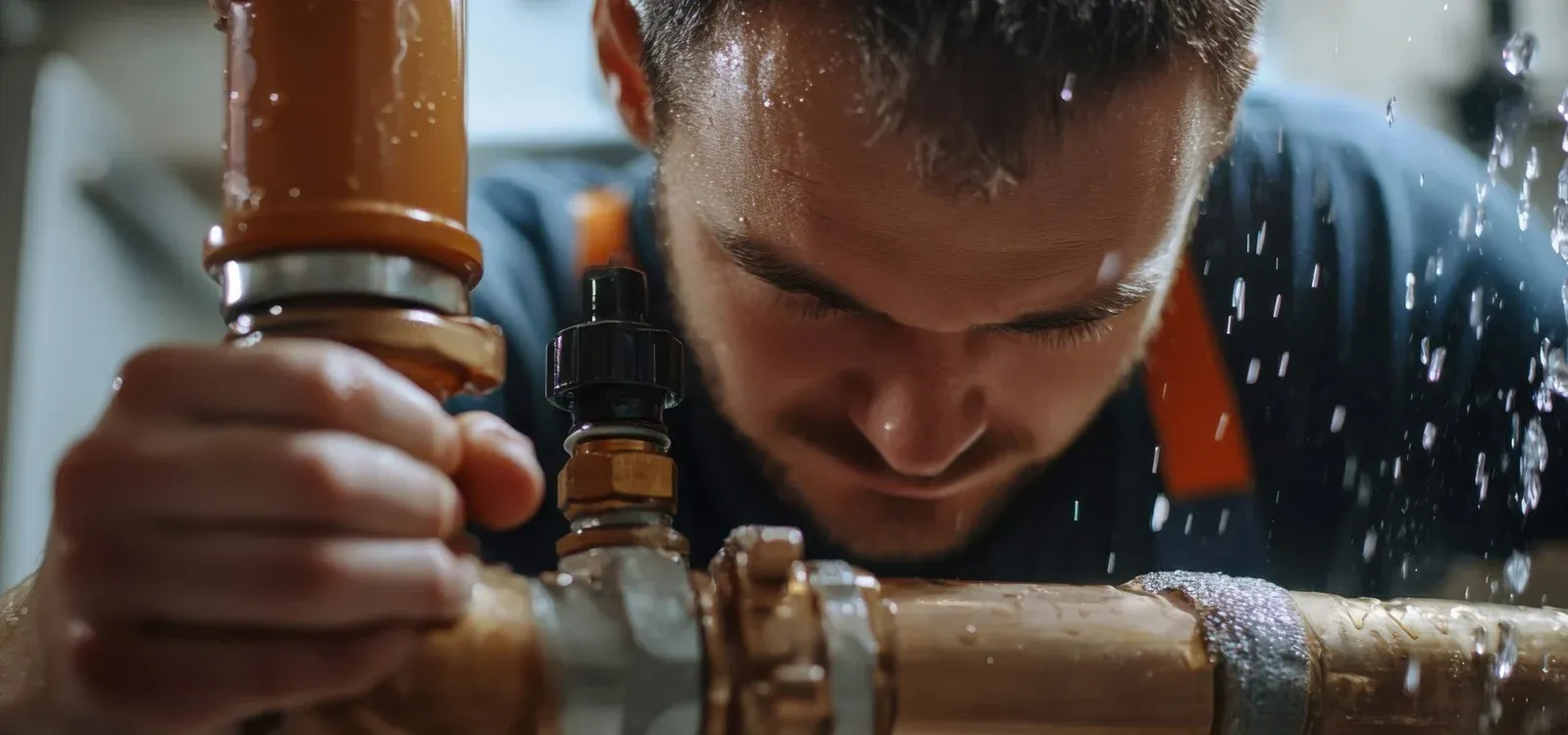
Hot Water System Leak Detection in Norwich
A hot water system leak in Norwich was located using a damp meter, thermal imaging, pressure testing, tracer gas, acoustic correlation, and visual inspection, completing hot water leak detection at a property in NR13 and allowing the system to be repaired and retested. The work was carried out by engineer Ferenc Gulyas.
 CIPHE accredited
 WIAPS member


Facts
| Location | Norwich |
|---|---|
| County | Norfolk |
| Leak Type | Hot Water Leak Detection |
| Property Type | Residential property |
| Detection Method | Damp Meter, Thermal Imaging, Pressure Testing, Tracer Gas, Acoustic Correlation, Visual Inspection |
| Outcome | Leak found on hot feed copper pipe beneath bedroom floor, repaired. |
Symptoms

The internal stopcock, located in the bathroom behind the toilet, was found to be non-functional, leaving no straightforward way to isolate the supply internally. The water meter was situated in the public footpath area.
With damage spread across the bedroom and bathroom zone, a structured hot water leak detection approach was needed to determine which part of the system was responsible and to pinpoint the exact leak location before any floor was broken.
Methods Used

To narrow down which circuit was responsible, the cold feed at the boiler was isolated and pressure testing was repeated on the external mains and cold feed alone — that test passed. Pressure testing on the hot feed pipework in isolation then failed, confirming the leak was on the hot side.
This is a standard progression in hot water leak detection: eliminate circuits systematically until the fault is isolated to one. With the hot feed confirmed as the source, tracer gas was introduced and the detector identified a likely leak location in the bedroom area.
Acoustic equipment was then used to refine the position as precisely as possible before any concrete was lifted.
Damp Meter. Used to survey moisture levels across the bedroom and bathroom area, returning high readings almost everywhere and establishing the extent of water spread beneath the floor.
Thermal Imaging. Used with hot water running to trace the pipe runs through the concrete floor, mapping the layout of the pipework before pressure testing began.
Pressure Testing. Applied in stages — first to all circuits together, then to the external mains and cold feed in isolation, and finally to the hot feed alone — to identify which circuit was leaking.
Tracer Gas. Introduced into the hot feed pipework after pressure testing confirmed a leak on that circuit; the detector identified a specific location in the bedroom area as the likely source.
Acoustic Correlation. Used after tracer gas to pinpoint the leak position within the bedroom floor as precisely as possible before concrete was exposed.
Visual Inspection. Carried out on arrival to assess the extent of water damage, confirm the locations of the stopcock, water meter, and boiler, and establish the starting conditions for the investigation.
Investigation Process
-
1Visual Inspection on Arrival
The engineer inspected the property and noted massive water damage to the corridor and bedroom walls, a saturated concrete subfloor where carpet had been lifted, a non-functional internal stopcock behind the toilet, and the boiler location in the kitchen.
-
2Damp Meter Survey
A damp meter investigation was carried out across the bedroom and bathroom area. High readings were recorded in almost every location surveyed, indicating widespread water spread beneath the floor.
-
3Thermal Imaging of Pipe Runs
Hot water was kept running and a thermal imaging camera was used to identify the pipe runs through the floor, establishing the layout before pressure testing began.
-
4Full System Pressure Test
Pressure testing was carried out on the hot, cold, and external mains pipework together. The test failed, confirming a leak was present somewhere in the system.
-
5Cold Feed Isolated at Boiler
The cold feed pipework was turned off at the boiler to allow the external mains and cold feed to be tested separately from the hot feed.
-
6External Mains and Cold Feed Pressure Test
Pressure testing on the external mains and cold feed pipework in isolation passed, ruling out both circuits as the source of the leak.
-
7Hot Feed Pressure Test
Pressure testing on the hot feed pipework alone failed, confirming the leak was located on the hot feed circuit.
-
8Tracer Gas Investigation
Tracer gas was introduced into the hot feed pipework. The detector identified a possible leak location in the bedroom area.
-
9Acoustic Pinpointing
Acoustic equipment was used to refine the leak position within the bedroom floor as precisely as possible before any concrete was lifted.
-
10Customer Informed
The customer was informed of the findings and the potential solutions before any floor was exposed.
-
11Concrete Exposed and Leak Found
The concrete floor was opened at the identified location. One leak was found on the 3/4" copper pipework in the bedroom area.
-
12Repair Carried Out
The leaking section of pipework was cut out and replaced using new copper pipework and soldering fittings, with insulation applied to the repaired section.
-
13Retest and Reinstatement
A pressure test was carried out on the hot feed pipework only; the test passed, confirming no further leaks. Water pressure was restored to working order throughout the property.
Result & Outcome

The dehumidifier already on site should be kept running to assist with drying out the concrete and surrounding structure following the prolonged water ingress. With the leak repaired and the system retested, the property in NR13 is back to normal operation.
Suspect a leak at your property?
ADI Leak Detection specialists investigate leaks like this across the UK every day. No find, no fee terms apply on qualifying jobs.