
Central Heating Leak Detection in Burnham-on-Sea
A central heating leak in Burnham-on-Sea was located using pressure testing, tracer gas, and thermal imaging, with central heating leak detection confirming two separate leaks beneath a concrete floor within the heating system pipework. The work was carried out by engineer Artur Sowa.




The original leak detection company, est. 2011
Facts
| Location | Burnham-on-Sea |
|---|---|
| County | Somerset |
| Leak Type | Central Heating Leak Detection |
| Property Type | Residential property |
| Detection Method | Pressure Testing, Tracer Gas, Thermal Imaging |
| Outcome | Two leaks found and repaired beneath concrete floor near radiators. |
Symptoms
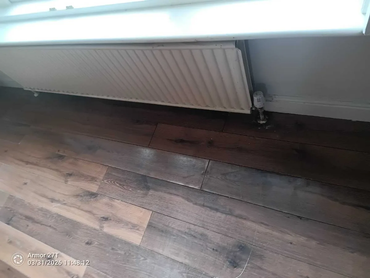
A property in TA9 presented with standing water in the living room, indicating a significant water ingress problem that required immediate investigation. The source was not immediately obvious from visible pipework or fittings, which pointed toward a concealed leak within the building fabric.
Initial pressure testing of both the internal cold water pipework and the external water supply pipe ruled out those systems — both held pressure without any detected drops. Further inspection of the loft revealed water escaping from the heating system's feed and expansion tank, confirming the heating system as the source.
This is a scenario where central heating leak detection becomes essential, as concealed heating pipework buried beneath concrete floors cannot be traced by visual inspection alone.
With the leak confirmed to be within the heating circuit and the pipework routed beneath a concrete floor, specialist detection methods were needed to pinpoint the exact location before any excavation could take place.
Methods Used

Once the heating system was drained, an air pressure test was carried out on the circuit to confirm an active pressure loss. Tracer gas was then introduced into the pipework and detection equipment was used to trace its path beneath the concrete floor.
A strong tracer gas reading near a radiator identified the first suspected leak area, allowing targeted excavation rather than wholesale floor removal. This approach is fundamental to central heating leak detection — it reduces unnecessary disruption while directing the repair precisely.
Following the initial repair, a further pressure test indicated a continued pressure drop, prompting extended tracing of the pipework. Additional concrete removal was required, and a second leak was identified and repaired.
A final pressure test on the complete system confirmed no further loss, establishing that the integrity of the circuit had been fully restored.
Pressure Testing. Used at multiple stages on this job to confirm active leaks in the heating circuit, verify the integrity of each repair, and confirm the system held pressure once both leaks were resolved.
Tracer Gas. Introduced into the drained heating circuit to locate escape points beneath the concrete floor, producing a strong reading near a radiator that directed the initial excavation.
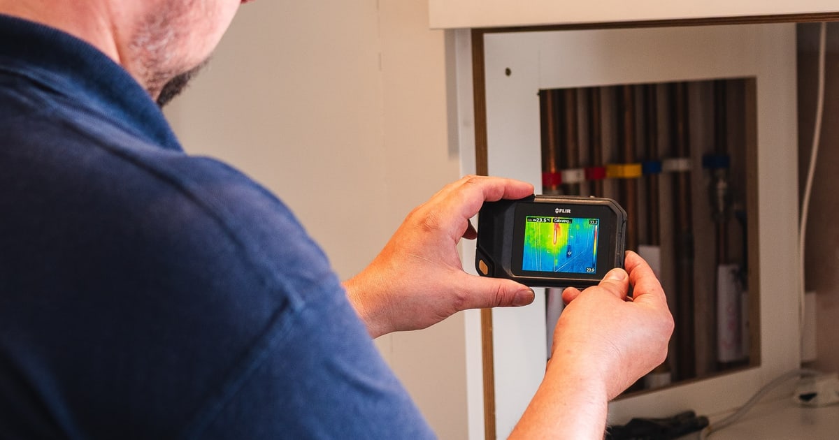
Thermal Imaging. Deployed during the investigation to assist in identifying temperature anomalies associated with water ingress and concealed leak paths within the property.
Investigation Process
-
1Arrival and Initial Observation
Standing water was found in the living room on arrival, indicating significant water ingress. The internal stop valve was isolated as a precautionary measure.
-
2Cold Water and Mains Pressure Tests
Pressure tests were conducted on both the internal cold water pipework and the external water supply pipe. Both held pressure without any detected drops, ruling these systems out as the source.
-
3Loft Inspection
Investigation in the loft revealed water escaping from the heating system's feed and expansion tank, confirming the heating circuit as the source of the leak.
-
4Heating System Drained
The heating system was fully drained in preparation for pressure and tracer gas testing.
-
5Air Pressure and Tracer Gas Test
An air pressure test confirmed an active loss in the circuit. Tracer gas was introduced into the pipework and a strong reading was detected near a radiator, identifying the first suspected leak area.
-
6First Concrete Excavation and Repair
Sections of the concrete floor were carefully removed to access the pipework at the indicated location. The first leak was found and repaired using press-fit slip couplings, press-fit couplings, and copper pipe.
-
7Pressure Test Indicates Second Leak
A pressure test on the repaired section still showed a pressure drop, indicating a further defect in the circuit. Tracer gas tracing was continued along the pipework.
-
8Second Concrete Excavation and Repair
Further concrete removal was carried out, and a second leak was located and repaired using the same press-fit and copper pipe method.
-
9Final Pressure Test
A pressure test on the entire heating system confirmed no further pressure loss, verifying the integrity of the repaired pipework.
Result & Outcome

Two separate leaks were identified and repaired within the heating system pipework at the property in TA9, both located beneath the concrete floor near radiator positions. The precision of the tracer gas detection method meant that excavation was targeted rather than speculative, limiting the extent of floor disruption required to access the defective sections.
Repairs were completed using 3 x 15mm press-fit slip couplings, 3 x 15mm press-fit couplings, and replacement 15mm copper pipe. The final pressure test across the full heating circuit confirmed no residual pressure loss, meaning the system is now structurally sound and fit for use. This outcome is typical of what central heating leak detection achieves — precise location, controlled access, and a verifiable repair rather than a process of elimination.
A power flush is recommended before the system is returned to full operation. Significant sludge and debris were observed within the pipework during the repair work, which left unaddressed could impair circulation efficiency and increase the risk of further corrosion or joint failure over time.
Suspect a leak at your property?
ADI Leak Detection specialists investigate leaks like this across the UK every day. No find, no fee terms apply on qualifying jobs.