
Central Heating Leak Detection in Watton
A central heating leak in Watton was located beneath the hallway floor using thermal imaging, tracer gas, pressure testing, and a damp meter, confirming central heating leak detection at a point directly in front of the downstairs radiator where a machine-bent copper tube had failed. Found by engineer Darren Smith.




The original leak detection company, est. 2011
Facts
| Location | Watton |
|---|---|
| County | East Riding of Yorkshire |
| Leak Type | Central Heating Leak Detection |
| Property Type | Residential property |
| Detection Method | Thermal Imaging, Tracer Gas, Pressure Testing, Damp Meter |
| Outcome | Leak found in hallway floor, failed copper bend replaced. |
Symptoms
At a property in IP25, the central heating system had been losing pressure over approximately 12 hours. The system comprised a system boiler feeding a radiator circuit, alongside an open vented hot water storage cylinder.
The ongoing pressure loss pointed to a leak somewhere within the heating pipework, though its location was not immediately apparent.
Visible signs of a problem were present at the downstairs WC: the laminate flooring on the right-hand side of the doorway was slightly raised, and the door itself was damp. Damp at the WC doorway was the clearest surface indicator, though the source of the moisture and the path of the leak remained unknown without a full central heating leak detection investigation.
Given that the pipework ran beneath a screeded floor, there was no straightforward way to identify the leak point without a methodical, equipment-led approach. The raised flooring and damp conditions suggested water had been tracking through the screed for some time.
Methods Used
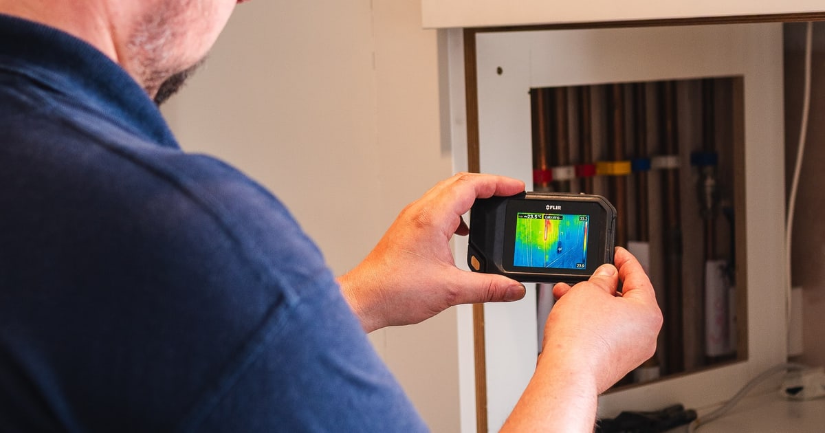
The investigation began with the boiler turned on and the heating pipework tracked using thermal imaging to identify any unusual warm patches on the floor that might indicate a subsurface leak. No such patches were found.
The pipework serving the downstairs WC radiator circuit was then drained using compressed air, and tracer gas was introduced through the downstairs WC radiator. A 30-minute pressure test at 2 bar was carried out, followed by a systematic check of the pipework route for escaping tracer gas.
No leak signal was detected.
With non-invasive methods exhausted, targeted excavation was carried out at the right-hand side of the downstairs WC doorway, where the floor had been raised. The screed beneath was damp and became progressively wetter toward the hallway, directing attention to a second excavation point in the hallway in front of the radiator.
This is a recognised approach within central heating leak detection — when gas cannot pinpoint a leak in buried pipework, carefully directed excavation based on moisture distribution is used to locate the source.
Thermal Imaging. Used with the boiler running to scan the floor for warm patches that would indicate heat from leaking heating pipework beneath the surface — none were found.
Tracer Gas. Introduced through the downstairs WC radiator after the circuit was drained with compressed air; the pipework route was then checked for escaping gas, but no leak signal was detected.
Pressure Testing. A 30-minute test at 2 bar was conducted after tracer gas was introduced, and again after the repair was completed, to confirm integrity of the heating circuit.
Damp Meter. Used to assess moisture levels in the floor and screed, helping to identify the direction of water travel and guide excavation toward the leak source.
Investigation Process
-
1Boiler activated and thermal imaging carried out
The boiler was turned on and the heating pipework was tracked using thermal imaging. No unusual warm patches were found on the floor.
-
2Raised flooring and damp door noted at WC
The laminate flooring on the right-hand side of the downstairs WC doorway was found to be slightly raised, and the door was damp.
-
3Circuit drained and tracer gas introduced
The radiator circuit was drained from the utility room using compressed air, and tracer gas was introduced through the downstairs WC radiator.
-
4Pressure test held for 30 minutes at 2 bar
A pressure test was carried out for 30 minutes at 2 bar. No pressure loss was recorded during this period.
-
5Pipework route checked for tracer gas
The full route of the pipework was checked for escaping tracer gas. No evidence of a leak was found.
-
6First excavation at WC doorway
The floor on the right-hand side of the downstairs WC doorway was excavated. The screed beneath was damp and became progressively wetter toward the hallway.
-
7Second excavation in hallway — leak located
A second area was excavated in the hallway in front of the radiator. A leak was found from a section of machine-bent copper tube that had ripped on the concave side of the bend.
-
8Leaking section cut out and renewed
The damaged section of pipework was cut out and replaced using 15mm couplings, elbows, and copper tube.
-
9Post-repair pressure test and system recommission
The heating circuit was pressure tested at 2 bar for 30 minutes with no pressure loss recorded. The system was filled, vented, and confirmed to be operating correctly.
Result & Outcome
The leak was located in the hallway beneath the floor in front of the downstairs radiator. A section of machine-bent copper tube had ripped on the concave side of the bend — a failure mode associated with pipe that has been bent under mechanical stress, which weakens the wall of the tube at the inner curve. Water had been tracking through the screed from that point toward the WC doorway, accounting for the raised laminate and damp conditions observed on arrival.
The damaged section was cut out and replaced with new 15mm copper tube, couplings, and elbows. Following the repair, the circuit was pressure tested at 2 bar for 30 minutes with no pressure loss, and the system was filled, vented, and returned to normal operation. The outcome is a good example of how central heating leak detection sometimes requires a combination of non-invasive methods and targeted excavation — when gas cannot locate a buried leak, moisture mapping and directed digging can still pinpoint the source precisely.
With the failed pipework replaced and the system holding pressure, the cause of the ongoing pressure loss has been resolved. The areas of excavation will require reinstatement of the screed and flooring as follow-on work.
Suspect a leak at your property?
ADI Leak Detection specialists investigate leaks like this across the UK every day. No find, no fee terms apply on qualifying jobs.